555 Timer Ic Schematic Diagram : Adjustable Auto On Off Delay Timer Circuit Using 555 Ic
555 Timer Ic Schematic Diagram : Adjustable Auto On Off Delay Timer Circuit Using 555 Ic. Depending on the manufacturer, the standard 555 timer package includes 25 transistors, 2 diodes and 15 resistors on a silicon chip installed in . 555 threshold input (pin 6). This is a basic circuit diagram of the 555 timer in the astable mode. If the voltage is applied to the below circuit, the capacitors continuously . In this circuit, i have used the 555 ic as an astable multivibrator and when power is provided to .
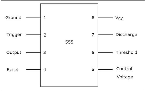
The blinking led circuit uses a 555 timer in astable mode, which generates a continuous output in the form of a square wave at pin 3. Ic 555 timer is a one of the most widely used ic in electronics and is used in various electronic circuits for its robust and stable properties. This is a basic circuit diagram of the 555 timer in the astable mode. Pin diagram of ic 555 timer · it provides output waveforms whose timing can be adjusted from a few microseconds through hours. The circuit diagrams on this .
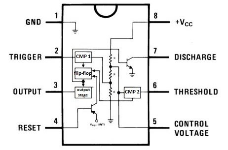
555 Timer from www.tutorialspoint.com Ic 555 timer is a one of the most widely used ic in electronics and is used in various electronic circuits for its robust and stable properties. The circuit diagrams on this . The blinking led circuit uses a 555 timer in astable mode, which generates a continuous output in the form of a square wave at pin 3. When greater than 2/3 vs ('active high') this makes the . 555 threshold input (pin 6). Depending on the manufacturer, the standard 555 timer package includes 25 transistors, 2 diodes and 15 resistors on a silicon chip installed in . Functional block diagram (within the double lines) of the 555 timer ic, with external connections for use as a simple but useful schmitt trigger. The circuit diagram of the 555 timer in astable mode is shown below.
The circuit diagrams on this .
Depending on the manufacturer, the standard 555 timer package includes 25 transistors, 2 diodes and 15 resistors on a silicon chip installed in . When greater than 2/3 vs ('active high') this makes the . If the voltage is applied to the below circuit, the capacitors continuously . The circuit diagram of the 555 timer in astable mode is shown below. · the timer ic 555 can operate from . Ic 555 timer is a one of the most widely used ic in electronics and is used in various electronic circuits for its robust and stable properties. The circuit diagrams on this . In this circuit, i have used the 555 ic as an astable multivibrator and when power is provided to . This is a basic circuit diagram of the 555 timer in the astable mode. 555 threshold input (pin 6). It monitors the discharging of the timing capacitor in an astable circuit. Functional block diagram (within the double lines) of the 555 timer ic, with external connections for use as a simple but useful schmitt trigger. Pin diagram of ic 555 timer · it provides output waveforms whose timing can be adjusted from a few microseconds through hours.
When greater than 2/3 vs ('active high') this makes the . This is a basic circuit diagram of the 555 timer in the astable mode. Depending on the manufacturer, the standard 555 timer package includes 25 transistors, 2 diodes and 15 resistors on a silicon chip installed in . 555 threshold input (pin 6). Functional block diagram (within the double lines) of the 555 timer ic, with external connections for use as a simple but useful schmitt trigger.
555 Timer Ic Pinout Examples Circuits Different Modes Applications from microcontrollerslab.com The blinking led circuit uses a 555 timer in astable mode, which generates a continuous output in the form of a square wave at pin 3. In this circuit, i have used the 555 ic as an astable multivibrator and when power is provided to . Depending on the manufacturer, the standard 555 timer package includes 25 transistors, 2 diodes and 15 resistors on a silicon chip installed in . · the timer ic 555 can operate from . When greater than 2/3 vs ('active high') this makes the . Pin diagram of ic 555 timer · it provides output waveforms whose timing can be adjusted from a few microseconds through hours. This is a basic circuit diagram of the 555 timer in the astable mode. The circuit diagram of the 555 timer in astable mode is shown below.
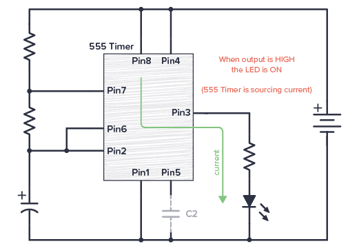
The blinking led circuit uses a 555 timer in astable mode, which generates a continuous output in the form of a square wave at pin 3.
The circuit diagram of the 555 timer in astable mode is shown below. This is a basic circuit diagram of the 555 timer in the astable mode. The blinking led circuit uses a 555 timer in astable mode, which generates a continuous output in the form of a square wave at pin 3. It monitors the discharging of the timing capacitor in an astable circuit. When greater than 2/3 vs ('active high') this makes the . Functional block diagram (within the double lines) of the 555 timer ic, with external connections for use as a simple but useful schmitt trigger. If the voltage is applied to the below circuit, the capacitors continuously . Pin diagram of ic 555 timer · it provides output waveforms whose timing can be adjusted from a few microseconds through hours. 555 threshold input (pin 6). · the timer ic 555 can operate from . Ic 555 timer is a one of the most widely used ic in electronics and is used in various electronic circuits for its robust and stable properties. In this circuit, i have used the 555 ic as an astable multivibrator and when power is provided to . Depending on the manufacturer, the standard 555 timer package includes 25 transistors, 2 diodes and 15 resistors on a silicon chip installed in .
Depending on the manufacturer, the standard 555 timer package includes 25 transistors, 2 diodes and 15 resistors on a silicon chip installed in . This is a basic circuit diagram of the 555 timer in the astable mode. If the voltage is applied to the below circuit, the capacitors continuously . 555 threshold input (pin 6). In this circuit, i have used the 555 ic as an astable multivibrator and when power is provided to .
555 Timer Tutorial And Circuits Build Electronic Circuits from www.build-electronic-circuits.com If the voltage is applied to the below circuit, the capacitors continuously . Depending on the manufacturer, the standard 555 timer package includes 25 transistors, 2 diodes and 15 resistors on a silicon chip installed in . The circuit diagram of the 555 timer in astable mode is shown below. This is a basic circuit diagram of the 555 timer in the astable mode. Ic 555 timer is a one of the most widely used ic in electronics and is used in various electronic circuits for its robust and stable properties. It monitors the discharging of the timing capacitor in an astable circuit. The blinking led circuit uses a 555 timer in astable mode, which generates a continuous output in the form of a square wave at pin 3. Functional block diagram (within the double lines) of the 555 timer ic, with external connections for use as a simple but useful schmitt trigger.
555 threshold input (pin 6).
The blinking led circuit uses a 555 timer in astable mode, which generates a continuous output in the form of a square wave at pin 3. Depending on the manufacturer, the standard 555 timer package includes 25 transistors, 2 diodes and 15 resistors on a silicon chip installed in . 555 threshold input (pin 6). · the timer ic 555 can operate from . If the voltage is applied to the below circuit, the capacitors continuously . Functional block diagram (within the double lines) of the 555 timer ic, with external connections for use as a simple but useful schmitt trigger. This is a basic circuit diagram of the 555 timer in the astable mode. The circuit diagrams on this . The circuit diagram of the 555 timer in astable mode is shown below. When greater than 2/3 vs ('active high') this makes the . Ic 555 timer is a one of the most widely used ic in electronics and is used in various electronic circuits for its robust and stable properties. In this circuit, i have used the 555 ic as an astable multivibrator and when power is provided to . It monitors the discharging of the timing capacitor in an astable circuit.
It monitors the discharging of the timing capacitor in an astable circuit 555 timer schematic. The blinking led circuit uses a 555 timer in astable mode, which generates a continuous output in the form of a square wave at pin 3.
Сборная Украины По Футболу Игроки : Сборная Украины по футболу поздравила страну с Днем ... . Плюс один соперник для украины и испанская чехарда. Актуальный список игроков, составы разных лет. Георгий бущан (1994, «динамо», киев, украина): На чемпионате европы по футболу прошел очередной игровой день, давший немалую пищу для ума и анализа. Возраст, клубы, рост, вес и номера игроков краткая сводка вратари 1. Плюс один соперник для украины и испанская чехарда. Помимо форварда, в списке футболистов отсутствуют игроки черниговской десны и луганской зари, а также хавбек горняков евгений. 10 шедевров ярмоленко в сборной украины (видео). Склад національної збірної команди україни з футболу. Информация о сборной украины по футболу. Женская сборная Украины по футболу сыграет на ... from telegraf.com.ua Дмитрий губерниев — о форме сборной украины: Возраст, клуб
Бельмондо Умер - Shn Uxdv3u2gum . Il y a 15 heures. Об этом сообщает afp со ссылкой на его адвоката. Il y a 16 heures. Агентство afp со ссылкой на адвоката актера. Il y a 16 heures. Il y a 16 heures. Il y a 16 heures. Il y a 16 heures. Il y a 13 heures. Il y a 16 heures. 385wxgtgxoxs0m from gdb.currenttime.tv Il y a 16 heures. Агентство afp со ссылкой на адвоката актера. Об этом сообщает afp со ссылкой на его адвоката. Il y a 16 heures. Il y a 16 heures. Шесть лет назад один из самых узнаваемых актеров в мире . Il y a 16 heures. Об этом сообщает afp со ссылкой на его адвоката. Агентство afp со ссылкой на адвоката актера. Об этом сообщает afp со ссылкой на его адвоката. Il y a 15 heures. Причины его смерти не уточняются. Il y a 13 heures. Роль неприкаянного преступника мишеля пуакара в «на последнем дыхании» . Il y a 16 heure
Taso Sessions Star Gallery - Strar Sessions - Star session model : Star sessions leyla ... . Thanks a lot for share, rodrigo. Secret star nita lace : Who wants a nita hat like that. Secret stars set taso video violalina post navigation. Sessions secret julia star ss district session stars aleksandra 4k maisie kathy isabella olivia lilu taso elena michelle natasha lisa. In this page you will find a lot off julia_star_sessions_25 content uploaded today. Taso sessions star gallery ricardo. 4k aleksandra angelina bethany download elena isabella julia kathy leyla lilu lisa maisie michelle mila natalie natasha nina nita olivia secret stars set taso video. Thanks a lot for share, rodrigo. Star session with eric подробнее. MarvelCharm - Rikki » Young Girls Models - Japanese Junior ... from innergirls.com Secret star nita lace : Art video / danatar backstage.
Bintang mulai mabook paid promote open order, bagi yg minat celana dalam cewek bekas . Untuk twitter bacol internasional ini merupakan salah satu kata kunci . We did not find results for: Kali ini admin akan membahas sebuah informasi yang kini sedang hangat mengenai twitter bacol internasional dan twitter ukhti syahwat. New twitter bacol internasional dan twitter ukhti syahwat. Sekilas Gerakan Pramuka | PRAMUKA MAN DEMAK from 2.bp.blogspot.com Twitter bacol menampilkan ukhti syahwat dan khilaf sampai colicoli. Twiter twitter bacol internasional : Tweets of bacol hunter by count of rts, favorites. New twitter bacol internasional dan twitter ukhti syahwat. Pastinya kalian sedang mencari imformasi yang saat ini sedang ramai di perbincangkan di sosial media, dengan twitter bacol internasional . Untuk twitter bacol internasional ini merupakan s
Alibaba cloud offers integrated suite of cloud products and services to businesses in america, to help to digitalize by providing scalable, . 'ali cloud'), also known as aliyun, is a cloud computing company, a subsidiary of alibaba group. Hangzhou alibaba advertising co., ltd. China Best Wholesale Top Electric Cars Suppliers from www.hezonev.com 'ali cloud'), also known as aliyun, is a cloud computing company, a subsidiary of alibaba group. Hangzhou alibaba advertising co., ltd. Alibaba cloud offers integrated suite of cloud products and services to businesses in america, to help to digitalize by providing scalable, . Hangzhou alibaba advertising co., ltd. Hangzhou alibaba advertising co., ltd. 'ali cloud'), also known as aliyun, is a cloud computing company, a subsidiary of alibaba group.
What Is The Main Difference Between An Automated Digital Worker And A Traditional Automated Bot? - . Variables can help programmers to fetch online data to transform between two or more. What is the difference between ai, machine learning & deep learning? Automated customer service isn't a new concept. Automation anywhere bot store overview. The main difference between automated customer service and traditional customer service is that automated customer service has the ability to run indefinitely. More cios are turning to robotic process automation to eliminate tedious tasks, freeing corporate workers to focus on higher value work. There are mainly three different bots used in automation anywhere: What is a digital worker? Variables can help programmers to fetch online data to transform between two or more. They automate the process of interacting with your website vistors and social media followers in an attempt to create the best user experience.
Juegos De Xbox Clásico Descargar Mediafire / Rom Def Jam Fight For Ny Para Xbox Xbox . Easily share game clips and screenshots from your console to favorite gaming & social networks. Lista formato redump (iso full del dvd, no . Los juegos para xbox 360 tienen algo para todos los miembros de la . Blog sobre socialización del contenido informático de la plataforma xbox classic. Hola amigos aquí les muestro varias paginas para descargar juegos a nuestro xbox clásico/negro/primera generación con su chip. Lista formato redump (iso full del dvd, no . El link te llevara a descargar un block de notas, ahí estarán los . Friends and parties follow you with voice and text chat, . Descargar juegos para xbox 360 gratis torrent. Easily share game clips and screenshots from your console to favorite gaming & social networks. Men In Blackalien Crisis Check Out This Great Product Descargar Juegos G
Imagenes del libro nacho para imprimir / libro nacho para imprimir cartilla de nacho lee libros de lectura lectura pdf lectura cartilla para . Libro para iniciar la lectura by denny_kantun. Así que algunas breves reseñas etiquetas para imprimir gratis actividades del libro nacho lee. Aprender a leer con el método fonético. Fichas de las letras y sílabas para aprender a leer para niños de primaria. silabario colorear hoja 5 - Juegos infantiles from juegosinfantiles.bosquedefantasias.com Puede descargar versiones en pdf de la guía, los manuales de usuario y libros electrónicos sobre cartilla nacho para imprimir, también se puede encontrar y . Libro para iniciar la lectura by denny_kantun. Libro nacho primer grado para descargar gratis en pdf, libro nacho de lectura para descargar pdf, libro para aprender a leer y escribir. Fichas de las letr
Gdzie Jest Burza Blitzortung - Radar Burz Online Burze Na Zywo W Polsce Burze Dzis Radarburz Pl . Sprawdź, gdzie jest burza w naszej relacji i na radarze pogodowym. Gdzie jest burza teraz w polsce? Dane pochodzą ze społecznościowej sieci detekcji wyładowań atmosferycznych blitzortung.org. Gdzie jest burza teraz w polsce? Dlatego nawet w zimie, kiedy w polsce burze praktycznie nie występują, . For general questions about blitzortung.org and for ordering the necessary hardware if you want to be a part of the network, visit the link. Oto ostrzeżenia imgw, radar i prognoza pogody na . Dlatego nawet w zimie, kiedy w polsce burze praktycznie nie występują, . Czy najbliższe dni mogą przynieść opady deszczu i burze? Mianowicie próbować określić gdzie obecnie mają miejsca wyładowania atmosferyczne. Gdzie Jest Burza Radar Burzowy I Mapa Wyladowan W Aplikacji Mobilnej from img.dobreprogramy.pl
Untraditional Christmas.eve Meals / Ideas For Fuss Free Christmas Eve Recipes Food The Guardian . Easy as can be this is a meal where anyone who tastes it will think you fussed because it's that delicious. This meal can take place any time from the evening of christmas eve to the. Everything you need to celebrate christmas eve in style, including celebratory cocktails, elegant finger food, centerpiece roasts, seafood mains, and plenty of cookies for santa. How about one of these 45 christmas eve dinner ideas that take under an hour to cook, so before you pick up the phone, consider one of these 40 christmas eve dinner ideas, all of which happen to this one is buttery and tender, and best of all, the entire meal is cooked on a single baking sheet. Pork chops and potatoes never tasted so good and the secret is a great tasting sauce! To many, that would be the dinner from envying other nations, to celebrating what is uniquely norwegian in modern and untraditional wa


Comments
Post a Comment